vurwill.blogg.se

Field effect transistor download


field effect transistor download

The regions are ohmic, saturation, cut-off and the breakdown region. The FET characteristics mainly depend on the various operating regions. These biasing techniques are chosen based on the necessity and the increment of the conductance values. Hence this circuitry is referred to as potential divider. The circuit is provided with the supply at the input but the two resistors are connected in such a way that the voltage at the input is divided with the help of resistors. These parameters can be controlled and they are not easily affected in the self-bias. Any changes in the transconductance values that reflect the distortion of the operating point.
field effect transistor download

(2) Self BiasĪs the name suggests if the external supply is not provided for the circuitry. The terminal gate must connect with the negative supply of the battery and no current flow is evident through the resistor. (1) Fixed Biasįixed bias in the FET can be obtained by supplying with the battery voltage. It can be fixed bias, self-bias, and the potential- Divider biasing.
field effect transistor download

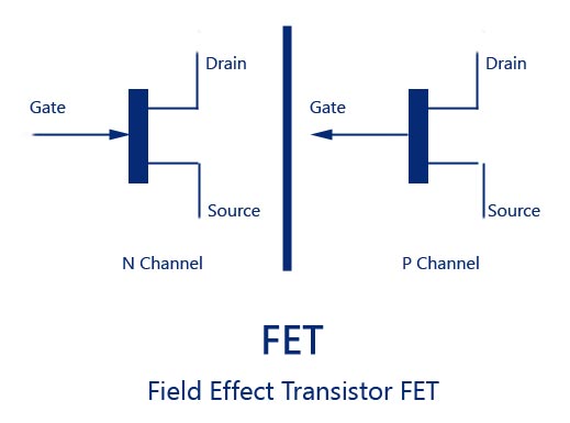
The FET biasing is also done like transistor biasing. Only the variation at the polarities of the supplies makes the FET work as p-channel JFET.

  • When the JFET is in its ideal mode there is no current evidence at the gate terminal.
  • The value of the input impedance is at a peak in this transistor.
  • The JFET is generally known for the characteristics of controlling the current by the application of the input voltages.
  • But certain increment at the voltages at drain and source the flow of current is stopped.
  • field effect transistor download

  • As this potential at drain tends to increase the flow of carriers increases the flow of current also increases.
  • Because of this condition, the majority of the charge carriers that are electrons flow can be seen from the terminals drain to the source.
  • Due to this reason, the width of the depletion region that is present near to the drain is greater in comparison with the source.
  • The junction formed due to the interaction of the drain and the gate terminal will be in reverse bias.
  • The drain terminal receives the highest potential in comparison with the gate in this n-channel JFET.
  • For the n-channel JFET, the positive side is connected to the source terminal.
  • Based on the channel it is known as n-channel JFET or the p-channel JFET.


  • Field effect transistor download